x86 Assembly Language Applicable To Reverse Engineering: The Basics – Part 2

For part 1 of this series, please click here.
Introduction

Become a certified reverse engineer!
We saw in the first article an introduction to the most common x86 assembly instructions seen when it comes to disassembling and analyzing programs. We talked about registers, the stack / pile, flags , conditional jumps and the instruction of comparison CMP. We will continue this part by introducing some mathematical and logical instructions, and some basic memory ones.
This is intended for beginners in reverse engineering who are still confused in front of the code shown by a disassembler.
-
Mathematical instructions
-
Multiplication : MUL / IMUL
- MUL instruction
-
Very useful, the CPU uses either the instruction MUL (for unsigned multiplication) or IMUL (for signed multiplication). To do multiplication, it multiplies an operand (a register or a memory operand) by AL, AX, or EAX registers and stores the product on one or more registers (BX, CX).
It behaves in the same way as MUL, except being used for signed operations, and preserves the sign of the product. Note that using the instruction CWD (convert word to double) is a must. Extending the sign of AX into DX is a must to avoid mistaken results.
-
Division : DIV / IDIV
- DIV instruction
Exactly the same as MUL and IMUL, DIV is used for unsigned divides and does division on unsigned integers.
Used for signed integer divides and using the same operands as DIV instruction, AL must be extended using the instruction CBW (convert byte to word) to the high order register which is AH before executing IDIV.
- The opposite of a number : NEG
A simple instruction, it requires a destination to which it inverses the sign, "+" becomes "-"or "-" becomes "+"
The result will be AX = -8
- Floating point numbers
And this is a real problem! x86 assembly cannot deal directly with floating point numbers, and has no specific register for them. The trick is using large numbers that would be divided to return a result in a given interval. This is Chinese!
To see how this actually works, let's suppose that we want to do 156 x 0.5, and admit that we want to put 0.5 into AX that does not accept floating point numbers. Well, let's multiply 0.5 by 256, which gives an integer: 128. Once we get our integer, we put it into AX, and now we can multiply 156 by 128, which leads to a result 256 time bigger then what we need, so we will divide the result by 256. This way we will get the result of 156 x 0.5 without using a single point.
Technically this sample will look like:
156 * 128 = 19968 divided by 256 =78 and this is equal to 156 * 0.5
- Negative numbers
At school when studying negative numbers things were really easy for us and mush easier for teachers , just add negative sign "-" and you got your negative number! Unfortunately things are a bit more complicated when it comes to x86 assembly code. In binary we cannot add "-"; there is only 0 and 1!
There is a method used that consists of:
- Converting the concerned number to binary.
- Reversing the binary bits (replace 0 by 1 and 1 by 0)
- Adding 1 to the result
Let's take 5 for instance. Five in decimal is equivalent to 00000101(Tab 1) in binary (actually 101 is OK but we need to work in 8 bit). By reversing bits we get 11111010 and 11111010
+ 1 gives 11111011. So -5 in binary is equal to 11111011.
Numbers
8 bits Binary representation
0
00000000
1
00000001
2
00000010
3
00000011
4
00000100
5
00000101
6
00000110
7
00000111
8
00001000
9
00001001
10
00001010
11
00001011
12
00001100
13
00001101
14
00001010
15
00001111
Table 1: Some Common Numeral Systems
- Logical AND
This instruction AND (destination, source) does a logical operation between two values and the result Tue is set to the "destination" if and only if the
destination and source are true. This means it sets 1 to the destination if and only if both operands are true, or else it sets 0 to the destination.
This does an inclusive "OR" between two operands, the result is set to the source. The result of "OR" is 0 if and only if both operands are equal to 0; otherwise the result is 1.
AND 00001100, 00011010 gives 00011110 (AX = 30)
- Logical exclusive or : XOR
Used in some cryptographic operations, it does an exclusive OR between destination and source. XOR is also considered as an addition with bites carry. The XOR is also used to reset the value of a register to zero; performing a XOR on a value against itself will always result in zero.
XOR EAX, EAX will result on EAX = 0
- Logical exclusive NOT
It does a logical negation on the specified operand and puts the result on the same operand. It inverses the value of a bit, bites that equal zero become 1, and vice versa.
The instruction TEST does a non-destructive AND (or a logical compare), and can alter flags depending on the result of the non-destructive AND between two operands / values.
If both of the corresponding bits of the concerned operands are equal to 0, each bite of the result is 0.
-
The memory and its instructions
- The instruction MOVx
To be able to put an offset in SI (Source Index Register), in assembly we do MOV SI, OFFSET but this is not applicable to Extra Segment, Data Segment, FS and BS registers.
To move entire memory blocs, we use MOVSB, MOVSW, or MOVSD depending on the amount of bits we want to move.
If we want to move n bits using the instruction MOVSB, we need to repeat this instruction n times, but before we need to "prepare / configure" Counter Register (CX) with how many time we want to loop. For this we use an instruction called REP.
Let's suppose we want to move 1000 bits:
This sample shows that 1000 bits are equal to 500 Words which is equal to 250 DWords
Quite similar to MOVx, this instruction is used to store string data. It transfers the content from the registers EAX for an address size attribute of 32 bits (or AL and AH for an address size attribute of 12 bits) to the memory passing from the destination register Extra Segment (ES register). The destination operand must be ES:DI. So to put 50 bits of zeros in ES:DI we have to do:
Conclusion
You have to be aware of the fact that part one and this second part do not pretend to teach you assembly programming. This a simple introduction to the most common instructions you will face when disassembling your first programs. These are the "important" instruction to know when looking at a disassembled program in order to understand how it partially works.
To see what I mean by this, have a look at the picture below:
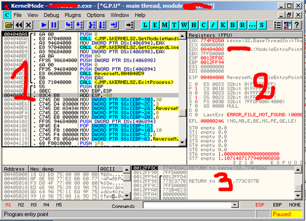
Figure 1. Disassembled program on OllyDBG
OllyDBG is (very basically) a tool that shows the assembly code of a compiled program, and it can let you execute this same program step by step, which means line by line or instruction by instruction. It's a 32 bits assembler analyzing debugger designed for Microsoft Windows platforms, it can trace registers, analyze code, recognize loops and APIs calls, etc. It can be attached to running program, and can trace every stack frame… you can find more about this tool in the references links.
Become a certified reverse engineer!
- Windows contains assembly instructions, and this is where we can go step by step when running a disassembled / debugged program, each line may alter and change data and values of Registers, memory and the stack.
- You can see the registers, flags and memory addresses.
- You can see the stack and different values that pass through it when analyzing a program.
References


- Exam Pass Guarantee
- Live expert instruction
- Hands-on labs
- CREA exam voucher
In this series
- x86 Assembly Language Applicable To Reverse Engineering: The Basics – Part 2
- CompTIA CySA+ Salary: What to expect in 2025
- How to become a cybercrime investigator
- CEH version comparison: V12 to V13 evolution guide
- SecurityX (CASP+) certification: Overview and career path [2025 update]
- Network+ certification: Overview and career path [2025 update]
- ISC2 CSSLP certification overview: What you need to know
- ISC2 CGRC: Overview & career path
- CRISC certification: Overview & career path [updated 2021]
- PMP certification: Overview and career path [updated 2021]
- ISACA CDPSE certification: Overview of the new ISACA privacy certification
- CGEIT certification: Overview and career path [updated 2021]
- What is a cyber range?
- Microsoft azure certification: Overview And career path
- CEH salary guide: What Certified Ethical Hackers really earn
- Average SecurityX (CASP+) salary [2025 update]
- CompTIA Network+ certification — A 2025 salary analysis
- CompTIA CySA+ exam (CSO-003): Your guide
- CCSP salary: How much can you make as a cloud security professional?
- Average Security+ salary (2025): Your guide to a prosperous cybersecurity career
- Average CGRC (Certified in Governance, Risk and Compliance) salary
- CRISC Frequently Asked Questions (FAQ) [updated 2022]
- Average CSSLP Salary in 2021
- ISACA CDPSE exam details and process
- How To Become CGEIT Certified – Certification Requirements [updated 2021]
- How to pick the best cyber range for your cybersecurity training needs and budget
- CEH exam eligibility: Application process & requirements guide
- SecurityX (CASP+) frequently asked questions (FAQ) [2025 update]
- CISSP domains overview: Your complete preparation guide
- CCSP exam and CBK changes in August 2024
- Comprehensive guide to CompTIA Security+ domains (2025)
- Average CRISC Salary [2023 update]
- CGRC certification job titles and career outlook
- ISC2 CSSLP exam details and process
- ISACA CDPSE certification exam: Overview of domains
- An Introduction to the PMP: Exam Details and Process [updated 2021]
- CGEIT certification exam: overview of domains [Updated 2021]
- 10 Success Tips: How to Pass Your Certified Ethical Hacker (CEH) Exam
- Network+: Exam details and process [2025 update]
- SecurityX (CASP+): Exam details and process [2025 update]
- How to become CCSP certified: Certification requirements
- Certified in Risk & Information Systems Control (CRISC) Exam Overview [updated 2022]
- ISC2 CGRC exam details and process
- Best CSSLP study resources and training materials
- ISACA CDPSE domain 1: Privacy governance
- 10 Tips for PMP Certification Exam Success [updated 2021]
- CGEIT certification exam details and process [updated 2021]
- Certified Ethical Hacker (CEH) study guides & resources [updated 2025]
- CompTIA SecurityX resources: Videos, books, tests and more!
- How to get the CompTIA Network+ certification: Requirements and step-by-step instructions [2025 update]
- CySA+ exam objectives: The 4 domains that will be covered
Get certified and advance your career!
- Exam Pass Guarantee
- Live instruction
- CompTIA, ISACA, ISC2, Cisco, Microsoft and more!
CompTIA CySA+
Discover the latest salary trends for CompTIA CySA+ certified professionals in 2024. Learn what factors influence your earning potential in the cybersecurity field.

Cybercrime investigator
Cybercrime has hit record levels, with an expected $7 trillion USD to be made from cybercriminal activity by 2021. Investigating these sorts of crimes can be

EC-Council CEH
CEH v13 is the world's first AI-powered ethical hacking certification. Discover what's new, how it compares to v12/v11 and why it's a career game-changer.

CompTIA SecurityX
Explore the expert-level CompTIA SecurityX certification, what to expect on the exam, the career benefits and more.
