System Configuration of Biometrics-The Network Topologies
Overview of the Last Article
Whenever the term of Biometrics is conjured up of and spoken in a conversation, the thoughts of a Fingerprint Scanner or any other related hardware comes to mind. As our series on Biometrics has reviewed, there is much more to it than that.
For example, there are the databases which contain the Biometric Templates, and the very sophisticated mathematical algorithms which process these very same Templates and extract and/or record the raw images.

FREE role-guided training plans
There is also the sensor component to the hardware. This is only used on Physical based Biometrics. This is the part which from which the image raw image is captured. For example, it could be the fingerprint, the iris, the face, and even the pattern of veins from just underneath the palm or the fingertips.
However, there is another component which is not given a lot of thought or consideration to when a Biometric System is procured and installed. It is only after this process is started does the realization come into play about the networking component. This simply means how will the modalities be interlinked, or networked with one another.
As it has been noted, for very simple installations, a modality can operate in a standalone mode. This is very often referred to as a local installation. A perfect example of this is the Single Sign On Solution (SSO).
With an Iris Recognition or a Fingerprint Recognition System, the password can be entirely eliminated. These two devices are installed via a simple USB connection, and in today's Windows Operating System environment, the drivers are installed automatically.
However, now imagine if there are hundreds of these types of scanners. Rather than doing a local installation on each and every one of them, it would obviously be much easier to network altogether in some sort of fashion (such as Peer to Peer Network).
Now consider this scenario: It is not just the SSO application which will be served, but there are others which will make use of Biometrics as well (such as that of Physical Access Entry, as well as Time and Attendance), and other, differing modalities will be used as well. For these types of complex designs, the Client-Server Network model will work the best.
In the scenario mentioned above, the network must be planned out properly in advance, making use of the Biometrics Project Management plan, as has been previously reviewed. The network in which all of these modalities will be connected to one another must be effective, efficient, and optimized on a daily basis to ensure that the Verification and/or Identification transactions will be accurate.
Our last article introduced the importance of planning the network properly. Specifically, it reviewed the following topics:
-
Network Processing Loads:
This refers to the concept of ensuring that the network is properly balanced and that not one modality is doing all of the work. In other words, all of the devices which are connected have their "workloads" proportionately equal, to make sure that there are no delays or lag times experienced.
-
The Data Packet:
This forms the basis of the communications (of any type or kind) across a network medium between two computers. In the world of Biometrics, this line of communication is between two Biometric modalities, or a Biometric Modality and a Central Server. Also, the subcomponents which make up a Data Packet were also reviewed.
In this article, we continue with and expand the theme of System Networking in Biometrics, now focusing upon the specific topologies.
Data Packet Switching

A very important aspect of Biometric network design is what is known as "Data Packet Switching." For example, when at least three or more Biometric devices are connected, or when a Biometric device is connected to three or more Central Servers, different network routes may be used to reach the destination Biometric Device or the Central Server.
This is done to optimize the flow of Data Packets in the overall Biometric network system design. At this point, a key question often gets asked: What makes the connection possible between the Biometric devices and the Central Servers? The answer lies in the Network Protocol.
Network Protocols
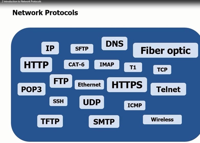
A Network Protocol can be defined as "the format and the order of messages exchanged between two or more communicating entities, as well as the actions taken on the transmission and/or receipt of a message, or other event." (SOURCE: 1).
Today, all Biometric devices connected with each other have to use certain Network Protocols to transmit their Data Packets back and forth. There are many Network Protocols which are in existence today. These include very specific Protocols for Open Source Applications, Closed Source Applications, hardwired connections, and wireless connections.
A Review of the TCP/IP Protocol
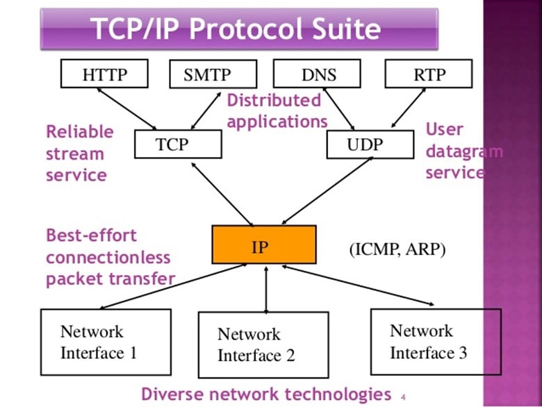
In the world of Biometric System Architecture, the Network Protocol known as "TCP/IP" is what is used most commonly. In fact, this particular Network Protocol is what is used in most applications that relate to the Internet. TCP/IP is actually a combination of two other Network Protocols.
TCP stands for the Transmission Control Protocol, and IP stands for Internet Protocol. This combination protocol of TCP/IP is a very powerful one, and in fact, it goes as far back as the 1970s, when it was first conceived for the ARPANET, which is the very first version of the Internet.
TCP/IP consists of four distinct network layers:
-
The Link Layer:
This layer consists of the communication tools used in the Biometric network so that the Data Packets that contain the Biometric Templates can travel from one link to the next link until they reach the destination Biometric Device or the Central Server.
-
The Internet Protocol:
This is the IP component of the TCP/IP Protocol and is primarily responsible for the internal communications between the various network links that make up the entire network segments between the Biometric devices and the Central Server.
-
The Transport Layer:
This is the TCP component of the TCP/IP Protocol and is primarily responsible for the overall communications between the Biometric devices and the Central Server.
-
The Application Layer:
This is where the overall TCP/IP Protocol resides and is responsible for all of the processing services that take places, such as the Verification and/or Identification transaction processing.
The Client Server Network Topology
In the Client-Server Biometric network, the server is known as the "Host," and the Biometric devices that connect to it are called the "Clients." This is illustrated below:

The Clients in this kind of Network Architecture merely transmit the Biometric Templates and other relevant information and data to the Host. It is from here that the Host then conducts and processes the Verification and/or Identification transactions, at the level of the database (which was reviewed in a previous article).
The Host is always in an "On Mode," and the Client can either be turned "On" or "Off" depending primarily on what time of the day (or even night) that they are needed. The transmission of the Biometric Templates to the Host is known specifically as "Network Requests." In other words, the Client is asking the Host to confirm the identity of the individual in question and to send the result of this transaction back to the Client.
Another notable feature of the Client-Server Network Topology is that the Clients never really technically communicate with another (but they can still be interlinked with one another if the Security requirements dictate so).
The Client only communicates through the Host; this is so because it has a unique TCP/IP address which is attached to it. Based upon this, the Client(s) know which Host(s) they need to send their respective Network Requests to.
Depending upon the scale and magnitude of the Client-Server Network Topology, often just using one Host is not enough to process all of the Verification and/or Identification transactions and to store the Biometric Templates in.
Very often, two or more Hosts are needed and depending upon the budget of the business or corporation as well as the total number of the end user population; a Server Farm may be required. In these instances, many Hosts (or Servers) will be required.
The Peer to Peer Network Topology
In a Peer to Peer Biometric Network, there are no main Hosts that are required. In this situation, the Clients are all networked amongst one another, and instead of assuming that role, the Clients (also the Biometric devices) become known as "Peers." See the following diagram for an example of a Peer to Peer Network:
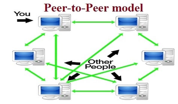
For example, if the processing of Verification and/or Identification transactions become too much for one Peer to handle, then the workload can be transmitted across to the other Peers since they are all networked together. There are two key advantages of the Peer to Peer Network: 1) Self scalability; and 2) Cost savings.
For example, with the former, each Peer adds on processing resource capabilities because the workload can be shared among all of the Peers, as opposed to just a few Hosts (the Servers). Also, since the processing of the Verification and/or Identification transactions is conducted with each Peer, the processing time is much quicker as opposed to the Client-Server Network Topology.
This is so because the Biometric Templates and the relevant metadata have to be transmitted back to the Host for all of this processing to take place.
With regards to the latter, since the Peers are also Hosts to a certain degree, there is no need acquire a central, dedicated Host. Also, a combination of a Peer to Peer and a Client-Server Network Topology is possible. This type of network configuration is known specifically as a "Hybrid Network."
As it has been discussed previously, Packet Switching is often used to help the Data Packets follow the most optimal network route to reach the next Biometric device or Central Server. However, it should be noted that Packet Switching is not used in most typical system network architectures; rather it is only used in the largest of Biometric applications.
A typical example of this is that of the large AFIS databases maintained by the FBI for to track down known criminals and suspects. Packet Switching is used at every moment here because Verification and/or Identification has to take place in just under two seconds.
Routers
To help further optimize the flow of the Data Packets in a very large Biometric System Network, Routers are often used to help break down the maze of network connections from the Biometrics devices and the Central Servers.
In technical terms, a Router can be defined as a "data table stored in a Router that lists the routes to particular network destinations, and in some cases, metrics (the distances) associated with those routes. It is a data file in RAM that is used to store route information about directly connected and remote networks. The routing table contains network/next hop associations." (SOURCE: 2).
In other words, a Router can be used to help literally create a group of smaller networks amongst a huge, overall Biometric Network System topology. These smaller networks are known specifically as "Subnets." An example of a Router can be seen below:
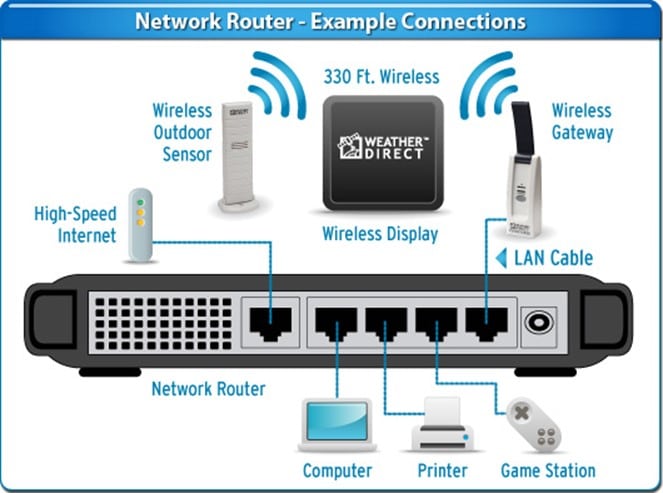
Apart from Data Packet Optimization, Routers are also used to help the System Administrator to fully map out and understand the logistical flow of Data Packets between the Biometric devices and the Central Servers.
As a result, the flow of Data Packets will be much smoother and efficient, and because of this, the transaction processing times of both Verification and Identification applications will also be that much quicker, especially in large scale applications.
Essentially, the primary goal of the Router is to forward the Data Packets containing the Biometric Templates along to the right destination (whether it is the next modality or a Central Server).
This is accomplished by collecting the information and data from the header of the incoming Data Packets which are going into the Router. Obviously, the Router by itself is not going to know the most optimal path to send the Data Packets; thus it uses what is known as a "Routing Table."
The Router consists of the following components:
-
The Input Ports:
This is where the incoming Data Packets first come into, and it is this same point that also helps send the Data Packets into the right direction into the Switching Fabric.
-
The Switching Fabric:
This piece of hardware is located directly inside of the Router, and this connects and acts as a bridge between the Input Ports and the Output Ports.
-
The Routing Processor:
This is similar to the CPU and the RAM of the Router. It contains and manages all of the Routing Tables and helps to a smaller extent the other various network management tasks.
-
The Output Ports:
This port sends the Data Packets onto its final destination (whether it is the next Biometric Device or the Central Server(s). Of course, before the Data Packet is sent out from here, the most optimal path is first calculated by the Routing Table.
The Routing Table
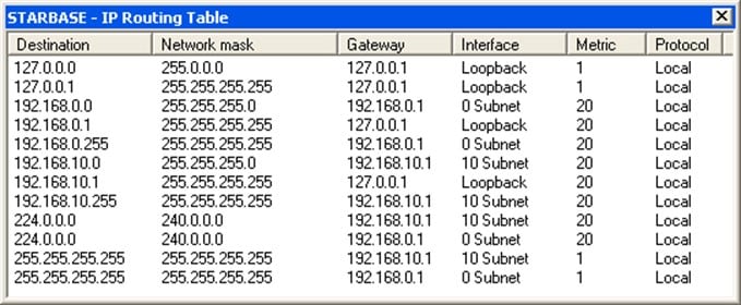
In simpler terms, a Routing Table is merely a map which is inside of the Router that tells it where to send the incoming Data Packets upon which appropriate outgoing network link(s) to ensure that the Data Packet reaches the right destination.
A Routing Table can also calculate the total distance that is required to send the Data Packet to the destination Biometric device or Central Server(s). To help even further with the optimization of this, the shortest routes are utilized as much as possible. A Routing Table is illustrated below:
Network Traffic Collisions
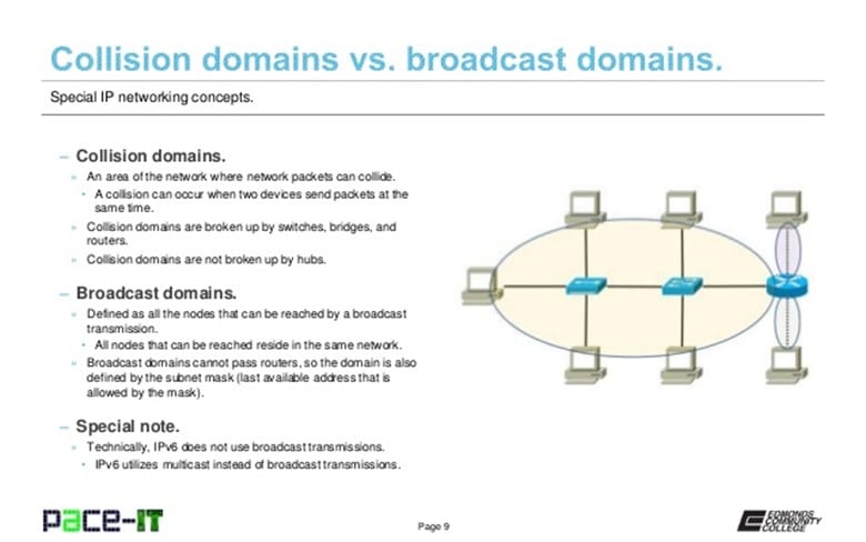
Although it does not happen very often, because the Biometric System Network Topology is a highly specialized one which only serves a few purposes. However, from time to time, the Data Packets can get backed up at the main point of entry of the Incoming Port. This can literally cause a traffic jam of sorts, thus further exacerbating the Verification and Identification processing ties.
How does such a situation get resolved? There are three primary methods:
-
The Tail Drop:
With this methodology, if the Router becomes too overloaded with incoming Data Packets, the excess of the Data Packets are merely dropped off from the incoming queue.
-
The Random Early Detection:
With this technique, statistical probabilities are calculated and assigned to every incoming Data Packet. This is used to help determine which Data Packets should get dropped.
-
The Weighted Random Early Detection:
In this method, statistical weights are computed and assigned to each incoming Data Packet to help ascertain which ones should get dropped.
Conclusions
It is important to note that a Router can be used in both the Peer to Peer and Client Server Network Topologies, although it is used in the latter instance the most. Also, since a Router has to examine and eventually determine the legitimacy of the incoming Data Packets, it can also act as a Firewall and even to help protect the overall Biometric System Network from any internal or external Security threats (such as those of Cyber-attacks).
This is accomplished when the Router discards and permanently deletes any malicious Data Packets from entering into the Incoming Port of the Router. However, keep in mind, there is still yet another weak link in the Biometric System: The network connections themselves, upon which the Data Packet traverses upon.
No matter how powerful of a Router or a Firewall is being used, these connections are still considered to be, in technical terms, wide open, and thus are prone to attacks and hacks. The best way to fortify them is to instill the principles of Cryptography, which is the focal point of our next article.
Sources
- Computer Networking: A Top Down Approach, Kurose, J.F., and Ross, K.W. Pearson Education, 2008.
- Computer Networking: A Top Down Approach, Kurose, J.F., and Ross, K.W. Pearson Education, 2008.
- http://iveeng.tripod.com/cn0202.pdf
- http://www.itrainonline.org/itrainonline/mmtk/wireless_en/04_Infrastructure_Topology/04_en_mmtk_wireless_basic-infrastructure-topology_slides.pdf
- http://catalogue.pearsoned.co.uk/samplechapter/0672321866.pdf
- http://www.cse.wustl.edu/~jain/cse567-08/ftp/topology.pdf
- http://www.ieee802.org/3/hssg/public/nov07/diminico_01_1107.pdf
- https://web.cse.msu.edu/~cse835/Papers/Sampling%20Algorithms%20for%20Pure%20Network%20Topologies.pdf
- http://www.cisco.com/c/en/us/td/docs/collaboration/CWMS/b_planningGuide/b_planningGuide_chapter_01.pdf
- https://www.ogf.org/documents/GFD.165.pdf
- http://www.ijcte.org/papers/719-A30609.pdf
- http://www.iject.org/vol4/spl3/c0116.pdf
- https://www.hh.se/download/18.70cf2e49129168da015800088934/Routers+and+Routing.pdf
- https://media.blackhat.com/us-13/US-13-Nakibly-Owning-the-Routing-Table-Part-II-Slides.pdf
- http://www.routeralley.com/guides/routing_table.pdf
- http://academy.delmar.edu/Courses/download/CiscoIOS/CiscoRoutingTable2_Lookup.pdf
- http://conferences.sigcomm.org/hotnets/2009/papers/hotnets2009-final156.pdf
- https://www.isi.edu/~johnh/PAPERS/Chang01a.pdf


